
Coverlay in Flex Circuit Construction
Whether they are designed for static or dynamic flexing and movement, coverlay is essential to the function of a flexible circuit. As the outermost layer of a flexible PCB, it provides critical protection from mechanical damage, dust, chemical substances and other environmental factors that could compromise the performance and reliability of the circuit. It also offers insulating properties, preventing current flow between the copper conductor patterns of different layers.
During the manufacturing process, traditional PCBs and flex circuits share many of the same steps. Both go through a wet processing phase that involves drilling, etching and photo-imaging. After the wet processes are complete, both go through an inspection and testing stage. However, after this point, the manufacturing process begins to diverge significantly. While rigid PCBs are able to go directly to the solder mask station, flex circuits must first pass through a coverlay station.
To protect a flex circuit, manufacturers use a layer of flexible polyimide film known as a coverlay. This material is much thinner than the adhesive used in a standard solder mask, and it comes in a variety of thicknesses to meet varying bending requirements. In addition, it is typically bonded with acrylic adhesives that are specially formulated to be flexible. The acrylic adhesives are also often “bikini cut” to ensure they do not extend more than.050” into the plated through hole areas of the design, which would otherwise cause reliability issues during the operation of the flexible circuit.
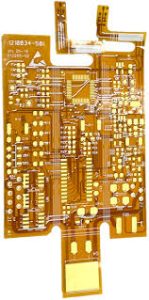
The Role of Coverlay in Flex Circuit Construction
The cladding openings in the coverlay are created using a variety of techniques, including laser cutting, routing and punch and die sets. The resulting pattern of openings is arranged to align with the copper conductor patterns and then laminated under heating and pressure. Unlike rigid PCB solder mask films, which have a fixed layer height, flexible coverlay has a variable layer height that allows it to better align with the surface of the flex and provide greater durability.
In order to prevent the aforementioned reliability issues, it is important to carefully review and specify the required coverlay opening sizes in the CAD file. This includes ensuring the required minimum bend radius is met for the design, and that there is adequate space to encapsulate the entire copper layer and any associated solder paste. In order to ensure that the flex circuit can meet these requirements, it is recommended that engineers consult their flex PCB manufacturer early in the design process to discuss these considerations.
In addition to ensuring that the correct coverlay is selected, it is also important to evaluate and analyze any potential fit and form concerns with the final product. This can be done by constructing a 3D virtual mock-up of the finished installed product in a CAD software package and reviewing the results for any interference issues. Investing a little bit of time in these steps can help to save valuable project time and money by ensuring that the right components are utilized in the resulting flex circuit.


